General description of measuring complex
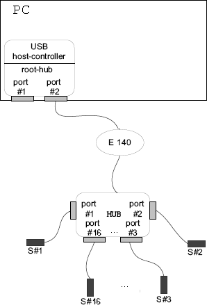
In this section you can find a scheme of measuring complex for measurements of physiological curves from a real human organism.
 The scheme of measuring complex The scheme of measuring complex |
|
 |
HUB – multi-channel voltage amplifier
S#1 – S#16 – invasive pressure sensors
|
|
|
On the picture there is a scheme of measuring complex with multi-channel voltage amplifier and sensors. As a source of analog signal you can use not only invasive blood pressure sensors, but also analog signals from other medical gadgets. For a coordination of output signals from measuring devices and input voltages of ADC Å140 use a special apparatus – multi-channel (to 16 channels) voltage amplifier with a range of output voltages ±10 V on the channels.
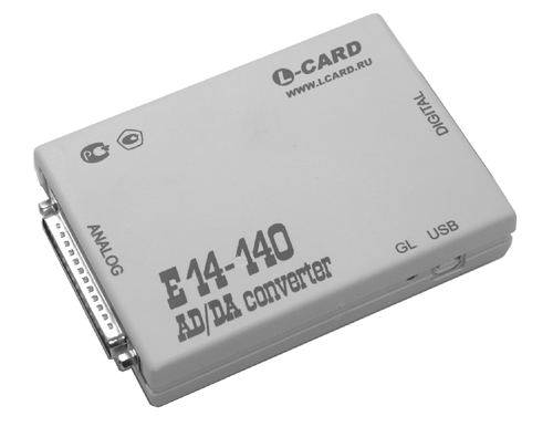
The program-technical implementation of measuring complex is based on ADC (module E140) produced by L-Card. It is intended for measuring of constant and alternating current, also for the input-output of analog data.
 Surface appearance of module Å-140 Surface appearance of module Å-140 |
|
|
Module E140 is a modern universal software-hardware device for use with standard consistent USB bus and is intended for construction of multi-channel measuring systems of input, output and processing of the analog and digital information consisting in personal IBM-compatible computers. This module is considered to be a compact and inexpensive device of multi-channel information gathering.
Using of USB-interface on module E140 gives to a user a lot of essential advantages. For example, at use of standard ADC/DAC devices for personal computers connected with ISA or PCI buses, there are some inconveniences, such as necessity of cardboard insertion in a computer, configuration of computer Setup for correct work of cardboards, impossibility of use of such cardboards with NoteBook portable computers. One of the possible variants of the decision of such problems when it is necessary to have the device which could be quickly and conveniently connected to a standard PC or to a NoteBook, is a use of external modules connected with USB bus.
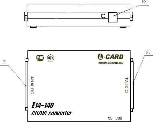
 Module Å140 Module Å140 |
|
 |
P1 - external socket for analog signals
P2 - socket for PC USB bus
P3 - external socket for digital signals (is not used)
|
|
|
Computer implementation > Measurements page > ADC measurements > General description of measuring complex
|


